| CHINESE

Preface
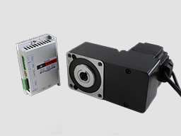
220VAC BL drives is a powerful driver designed by Dingtuo Technology independence which is assorted with the advanced motion control industrial. The drives adopt the latest DSP specialized for motor as the core technical matched with high speed digital logic chips and high quality power module. It gets the advantage on highly integration, small volume, well protection, high reliability etc. This drives can provide: panel speed adjust command, external simulative voltage, external potentiometer, pulse width speed adjust etc.
Product Characteristic
1. System Characteristic:
Input Voltage: AC180/250VAC, 50/60Hz,
Continuous Output current: 8A, suit for less than 1500W brushless motors
Max. Output current: 15A,
Working temp.: 0~+45°C
Storage temp.:-20~+85°C
Working & storage humidity: <85% no frosting
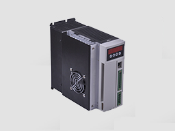
Structure: wall-mountable box type <
Dimension:L180 x W100 x H210mm
2. Basic Characteristic
Cooling: Radiator
Control terminals :Isolation
Protection:Over load, over heat, over speed, over voltage, lost voltage will cause the power abnormity.
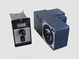
Panel:6 digit LED display, 4 digit keypad operation
Power Terminal and Motor Terminal
No. | Terminal Name | Signal | Function |
1 | L1(L)(R) | Power input of main circuit | Main circuit power input terminal AC220V 50Hz, Connect L1 and L2 while using single phase voltage 220V |
2 | L2(N)(S) | ||
3 | L3(T) | ||
4 | P | High voltage DC bus line terminal | DC bus line terminal in driver, rated power 315V |
5 | B1 | internal brake resistance | When using internal brake resistance, short circuit B1 and B2, when the power is not enough, need to use external brake resistance, break B1 and B2, connect external brake resistance with P and B2 |
6 | B2 | external brake resistance | |
7 | U(MA) | Output | The motor terminals must be connected with U,V,W one-to- one. Attention: do not reverse the motor by exchange 3 phase terminals, it is completely different with asynchronous motor |
8 | V(MB) | ||
9 | W(MC) | ||
PE | Protection | The release way is supplied for protection motor and drive when current leakage |

Parameters setup
3.1 Parameters P1
This series characteristics are used to set up some functions by clients self, they can be self-adjust according to clients’ different demand. They are operation functions, have no relation with fundamental characteristics of driver
Function Name | No. | Value Range | Default Value | Function Specification |
Display optional | P1。0 | 0~9 | 0 | 0. display real speed 1. display DC voltage of main circuit 2. display external analog input 3. display motor current 4. display internal program speed 5. U phase current 6. V phase current 7. W phase current 8. duty ratio 9 .preserve |
Internal running speed | P1。1 | 0~9999 | 2000 | When choose internal speed, the data will decide motor’s speed(view P1。2) |
Choose signal sourcing of speed | P1。2 | 0~2 | 1 | 0:internal instruct speed(tP1[0] is internal speed, when motor running, MUP to up speed ,MDOWN to reduce speed) 1: external terminal analog input, using SV signal of 7 pin of CN2 as motor’s speed. 2:communication order control |
Direction setting | P1。3 | 0~1 | 0 | 0: CW 1: CCW |
Choose signal sourcing of start-stop | P1。4 | 0~2 | 1 | 0:button by hand control(ENT is start-stop, SET is reverse motor, +/- is for up and reduce speed) 1:external terminal control: using 4pin signal of CN2 to start and stop motor 2: communication order control |
pole pairs of motor | P1。5 | 0~99 | 2 | attention: pole pairs=pole/2 |
Driver location | P1。6 | 0~255 | 0 | The driver location when Using communication to control motor |
Speed scale factor | P1。7 | 0~99999 | 1520 | Scale factor using for PID speed control (KP) |
Speed integrating factor | P1。8 | 0~99999 | 320 | Integrating factor using for PID speed control(KI) |
Accelerated speed | P1。9 | 1~60000 | 6000 | The parameters is directly proportional to accelerated speed, the real accelerated speed is based on loading of motor |
Decelerated speed | P1。10 | 1~60000 | 6000 | |
Rated speed setting | P1。11 | 0~99999 | 3000 | Speed corresponding maximum analog input (unit: RPM) |
Analog input dead band | P1。12 | 0~3300 | 100 | The function is used to set input voltage when motor speed is 0 (unit: mV) |
Manual operation to adjust speed equivalent | P1。13 | 1~999 | 1 | Use bottom to change the speed equivalent under internal speed type ( speed changed per press) |
Recover default parameters | P1。14 | 0~1 | 0 | Set up 1 then quit setting, connecting the power again, all parameters will recover to default value. |
3.2 Control panel operation

As picture on left, there are 4 keys on the panel,
“SET”: press this key can enter or quite P1 setup menu
“▲”and “▼”: “+”and “-”,to choose the function and adjust the parameters. Otherwise, “+”is the hotkey to enter trial operation function.
“ENT”: “confirmation” and “operation”, when setting parameters, press this button to enter adjustment interface and jump. Under trial operation type, press ENT to start or stop motor.
Display instruction: total 6 digital tube shows “888888”, the light most is first and the lowest
Attention: The adjustment is forbidden if the adjusted value is larger than the maximum allowed, the bottom will be no response.
3.3 How to set parameters
Example:
Demand: set internal speed (P1.1) to 1000rpm/min
Operation step as below:
1. After connecting with power, display “H 0”, the driver is standby, press “SET”, will display“P0。 0”
2. Press “SET”, display “P1 0”, the driver is entering P1 setting state
3.Press “▲”, until display “P1。 4”
4. Press “ENT”, display “2000”, and the first of light most is flashing
5. Press “ENT”, until the flashing is moving to the fourth position
6. Press “▼”, change into “1000”
7. Press “SET”, display “P1。 4”, the parameters had been set up and save automatic
8. Press “SET” again, display “P2 0”
9. Press “SET” again, back to standby state, display “H 0”, now, the new parameters adjustment had finished and take effect
Attention:
1. after adjustment, the driver need to connect with power again, then the new parameters will take effect
2. The parameters with “★” in the list can not been adjust when motor working
3. The adjustment is forbidden if the adjusted value is larger than the maximum allowed, the bottom be will no response
Wiring Diagram 
Functions
1. Speed adjustment method
This driver provide below three adjust methods for the user to choose:
Analog voltage adjustment speed: the terminals of external potentiometer connect to the +5v terminal in signal control and COM, connect the regulator terminal to SV, not only make it possible to adjust speed by external potentiometer (10K~100K), but also can achieve speed adjust through other control unit (Such as PLC, Microcontroller, etc) input analog voltage to SV. The acceptance of SV is DC 0V~+5V, and the corresponding motor rotate speed is 0 to rated speed.
You also can use external digital signal to adjust speed: apply PWM with 5V amplitude and 1KHz~2KHz Frequency between SV and GND to adjust the speed. The motor rotate speed will adjust by the duty radio liner adjustment.
The third method to adjust speed is using communication order controlling
2. Motor operate/stop control (EN)
You can control the brushless motor to run or stop by controlling the terminal “EN” and “COM” connecting. The motor will run when we connect the terminal “EN” to “COM”; when shut down, the motor will stop naturally. And the starting time will decided by the initial setup in panel, the motor running will be affected by load added
3. Motor rotation direction control ( F/R )
You can control the motor rotation direction by controlling the terminal “F/R” and “COM” connecting. When connect terminal “F/R” to terminal “COM”, the motor will run at CCW (view from motor output side), and when shut down, the motor will run at another direction.
Attention: If you need to change the motor rotation direction, please stop the motor at first, otherwise the controller shall be caused to damage.
4. Break the motor to stop ( BK )
You can break the motor to stop if need. Motor can be running when the terminal “BK” not connect to “COM”, but if you connect these two terminal together, motor will stop quickly. If the overload alarm frequently, you need to add brake resistance for driver, the resistance value is not less than 100Ω, and power is not less than 100W. Attention: when install the brake resistance, the driver must be under without power and indicating light state. The brake resistance accessories is for charge
5. Speed signal output (PG)
The speed pulse output is 0C, output 30V/10mA max. You can connect with a resistance (3K ohm ~10K ohm) between “PG” and the input power to get the speed pulse signal. The relationship of output frequency F(Hz) and speed N(rpm)is: F=N * P / 60 , P is the pole pairs of motor, Output Pulse per revolution.
6. Alarm output (ALM)
The alarm output port is 0C, output 30V/10mA max. You can connect with a resistance (3K ohm ~10K ohm) between ALARM output and the input power to get the alarm signal. When alarm, this port and the GND connecting (Low voltage), and the controller will stop working and keep in alarm status.
Working methods
The driver has three working methods by setting panel. The first is panel manual operation, press R/S to start or stop the motor, press + - to up or reduce the speed, press“ ←∣”ENTER to confirm the speed. The second is by external terminals, the motor is working with settle, digital tube display running speed. The third method is communication type.
Protection type
When the motor is running abnormally, the digital tube will display:
(1) OL motor locked。
(2) OC over current。
(3) HE hall signal failure。
(4) LV under voltage input 。
(5) HU over voltage input。
(6) EE IPM failure protection。
(7) OT motor too hot
System using
Firstly, connect motor and driver lines (wounding lines, hall signal lines and power line) in strictly observe related norms and specification. It can’t to reverse the motor by change lines connection, it is completely different with asynchronous motor. The motor and driver can not work normally even damaged if lines connected wrong
You can start the trial operation after connecting motor power line, hall line and driver power lines. At first, set the control panel or terminal control, secondly set the pole pairs of brushless DC motor (wrong pole pairs will display inaccurate speed and offer wrong inner parameter ), then press the start button, enlarge the potentiometer slightly , the motor will run, if the motor do not work, or shake, or alarm, maybe the lines connection is not correct, or load is too large, please check again, until the motor running normally.
Phone: 0755-25796858
Fax: 0755-25796696
Mailbox: sales@dt-me.com
Address: Xili, Nanshan District, Shenzhen, Guangdong Province
Contacts:Mr.Tong
Changzhou Office
Contacts:Mr.Tang
 |  | |
| Micro-scan sweep | Phone swept away |
 13332976238
 13088821218189753320201861565275118128820282
 外贸客服18926576949